The Making Of monotrino, Part 2
After a mere two week pause, a new status report on the build of my sequencer.
I’ve been puzzled quite some time about how to proceed with the build. The problem I was facing is: my wire is just too big. It was supposed to be 24 AWG (or ø 0.51mm, for the more Metric-oriented) when I bought it, but apparently I’m not good at measures :-) It turns out what really counts is the isolation diameter, which is 1.45mm.
It was ok to build the button-to-resistors connection, because I have a lot of headroom there – and I could use a lot of tin. But when it comes to soldering adjacent pins on a 0.1″ (or 2.54mm) header, it… just won’t fit.
I was wondering if I shouldn’t have used lead tracks instead of wires. But:
- I don’t have that much lead (the resistor legs I cut away, but that’s not enough).
- Laying out tracks is a lot of work :-)
- Fitting all the components plus the additional space for the tracks on my 16x10cm perfboard is going to be challenging.
And then, the solution suddenly appeared before me like in a dream! It was this simple: network cable. If you tear it open, it has 8 independent insulated wires inside, supposedly 22-24 AWG. Whatever this means. Anyway, much, much thinner than what I have. And they come in colors, too! :-)
So I sacrificed a ~1.5m network cable I had lying around, and it turned out it fits the job perfectly. The only drawback is that it’s not so easy to strip them (unless you have the right tool, which I don’t). I had to resort to using a pair of scissors and my teeth, which is quite time-consuming.
Armed with my new wires, I managed to fully connect the keyboard (eg. the 12 “note” push buttons). This means connecting all upper pins of the buttons together and then to an Arduino analog pin, and the lower pins of the buttons between resistors (which I did in part 1) and finally to the Arduino GND pin. Took me ~3 hours for this, including testing.
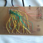
And this is the picture of the back side in its current state:
The green/orange/whitey wires (eg. those that are not yellow) are from the network cable. The difference is rather obvious :-)
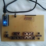
And this is the front side, with the Arduino in place:
I connected it and tested the keyboard using a simple sketch that outputs to the Serial Monitor. Nothing fancy, but seeing the result of all this hard work come to life (and actually work!) is insanely rewarding :-)
FYI, this is the sketch I’m using to check the buttons. It just prints “button N”, where N is the button you pressed. The part inside “if(0)” is used to calibrate the buttons. Change it to “if(1)” and you will get the actual analogRead() result. Then write down those numbers in the readButtons() function. They are really depending on the actual resistors, that’s why it needs calibration. I’m using standard carbon 1kΩ with 5% tolerance, and I had to adjust the numbers for buttons 1-4 between my breadboarded prototype and the actual monotrino keyboard.
#define AROUND(x, y) x >= y-10 && x <= y+10
#define BUTTONDELAY 20

int l = 0;
long buttonLastChecked = 0;
int lastAnalogRead = 0;

void setup() {
  Serial.begin(9600);
  pinMode(A5, INPUT);
  digitalWrite(A5, HIGH);
}

void loop() {

  if(0) {
    int a = analogRead(5);
    if(abs(a-lastAnalogRead) > 10) {
      lastAnalogRead = a;
      Serial.print("analogRead=");
      Serial.println(a);
    }
  }

  if( buttonLastChecked == 0 ) // see if this is the first time checking the buttons
    buttonLastChecked = millis()+BUTTONDELAY;  // force a check this cycle
  if( millis() - buttonLastChecked > BUTTONDELAY ) { // make sure a reasonable delay passed
    int b = readButtons();
    if(b != l) {
      if(b > 0) {
        Serial.print("button ");
        Serial.println(b);
      }
      l = b;
    }
    buttonLastChecked = millis();
  }
}

int readButtons() {
  int a = analogRead(5);
  if(AROUND(a, 247)) {
     return 1;
  }
  if(AROUND(a, 231)) {
     return 2;
  }
  if(AROUND(a, 213)) {
     return 3;
  }
  if(AROUND(a, 195)) {
     return 4;
  }
  if(AROUND(a, 177)) {
     return 5;
  }
  if(AROUND(a, 157)) {
     return 6;
  }
  if(AROUND(a, 136)) {
    return 7;
  }
  if(AROUND(a, 114)) {
    return 8;
  }
  if(AROUND(a, 92)) {
    return 9;
  }
  if(AROUND(a, 67)) {
    return 10;
  }
  if(AROUND(a, 42)) {
    return 11;
  }
  if(AROUND(a, 15)) {
    return 12;
  }
  return 0;
}
That’s it for today. In the next episodes: more buttons, hooking up the LCD and adding some knobs!
cheers,
Aldo
The Making Of monotrino, Part 1 The Making Of monotrino, Part 3


 Fritzing
 Makeblock
 narbotic
Comments are currently closed.